| BustedGear.com |
| Shop | Repairs | Manufacturers | Resources | iFAQs | About |
|
|
|||
| Yamaha® MOTIF 6 and 7 | 1: Right-Hand Switch Board | ||
|---|---|---|---|
|
Last Page < |
Page Bottom ∨ |
Next Page > |
|
|
|
|||
|
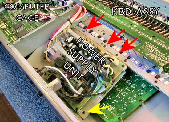
The MOTIF's power supply unit (PSU) must be removed before you can get to the right-hand switch board. If you did the MOTIF6-7 Disassembly, then the computer cage and the keyboard assembly, shown here, would already be removed. The PSU cables would also be disconnected. Three screws, marked with red arrows in this photo, hold the PSU to the MOTIF's right-hand mounting rail. Two more screws attach to a bracket on the rear-panel. One is marked with a yellow arrow in this photo. Another is unseen on the other end of the bracket. |
|
|---|---|
|
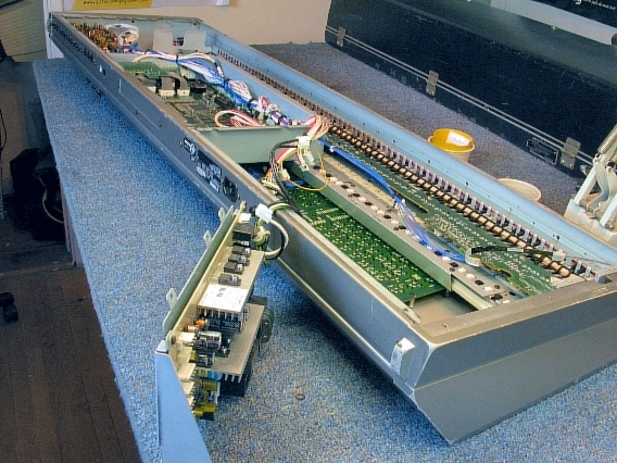
After removing the mounting screws, you can lift the PSU out of the MOTIF and rest it on the work surface as shown here. The wires to the AC inlet and the on-off switch are long enough to reach. |
|
|
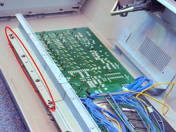
This photo shows the right-hand switch board after the PSU is taken out. You can now see the rear-panel bracket and the right-hand mounting rail. The mounting rail must be removed. Take out the five black screws circled in this photo. They hold the rail and the switch board to the MOTIF's shell. |
|
|
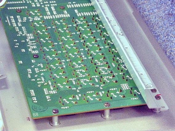
Take out seven more black screws holding the switch board to the shell. Five of these screws can be seen in this photo. |
|
|
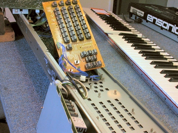
The right-hand switch board can now swing up and away from the shell, as shown here. The buttons' knobs stay attached to the printed circuit board. The data dial knob was pulled off before starting. |
|
|
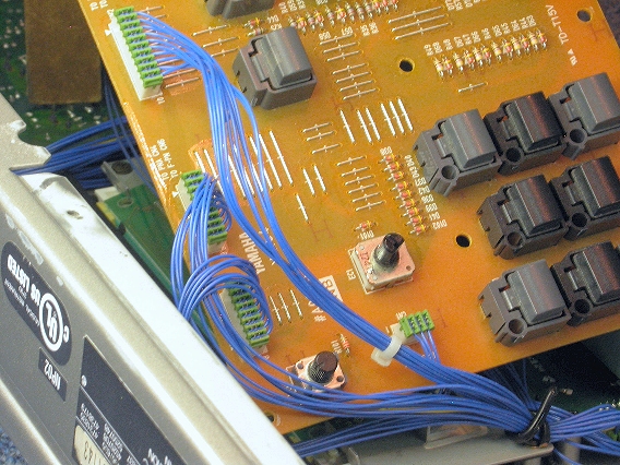
Disconnect the four cables, shown here, from the switch board. Each cable has a different number of blue wires. Pull the green cable headers out of the mating, white headers on the PC board. |
|
|
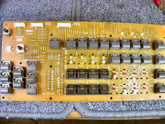
Now you can remove the knobs that sit above the worn-out tactile switches. The next page shows you how to do this. In this photo, three "blocks" of four knobs each have been removed. When you reinstall this board, be sure the 3 tall, yellow LEDs haven't bent over. The board must lay flat against its mounting stand-offs. Start all of the screws before tightening down any of them. Afterwards, carefully turn the unit over just enough to make sure all the switches click when you press them and the tall LEDs protrude thru the panel. |
|
| Yamaha® MOTIF 6 and 7 | ||
|---|---|---|
|
Last Page < |
Page Top ∧ |
Next Page > |
|
|
|
|
|
Page design and content Copyright © Richard Diemer - All rights reserved |