| BustedGear.com |
| Shop | Repairs | Manufacturers | Resources | iFAQs | About |
|
|
|||
| Korg® Poly-61M | 2: Troubleshooting the Envelope Generators | ||
|---|---|---|---|
|
Last Page < |
Page Bottom ∨ |
Next Page > |
|
|
|
|||
|
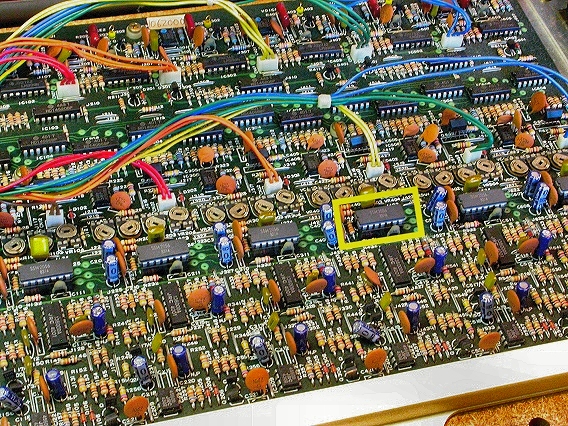
Here's a close-up of the Korg Poly-61's Voice circuit board. The Poly-61 is a six-voice polyphonic synthesizer (six notes can be played at once). The six sound envelopes are generated by six Envelope Generator chips, the now obsolete SSM-2056. In this photo, you can see the six EG chips. One of them is outlined in yellow. None of the envelopes were working properly in this synth – there was no control over attack and decay times. It was unlikely that all six of the EG chips were bad, but it was a convenient place to start troubleshooting. |
|
|---|---|
|
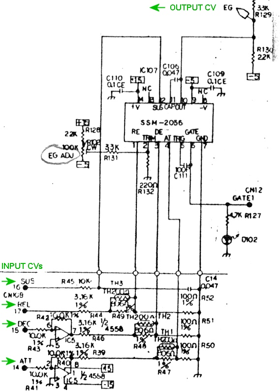
Here's one of the six SSM-2056 chips, as seen in the Korg Poly-61 schematic. ATTACK, DECAY, SUSTAIN, and RELEASE Control Voltages arrive at the bottom left and go to pins 4, 3, 12, and 1 of each chip. When a key is pressed, a gating voltage is applied to pin 6 of one of the chips, causing it to output a 4-stage voltage envelope on pin 10. Notice that the chips' ATT and DEC inputs are driven by IC5, a 4558 dual op-amp. We tested the ATT and DEC voltages on the inputs and outputs of IC5. They were stuck at zero volts and didn't change when new attack and decay times were entered on the front panel. So, the problem was somewhere upstream from IC5. |
|
|
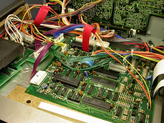
The CPU board, shown here, generates the four envelope control voltages. They're sent to the Voice circuit board via the flat foil cable seen at the right edge of this photo. |
|
|
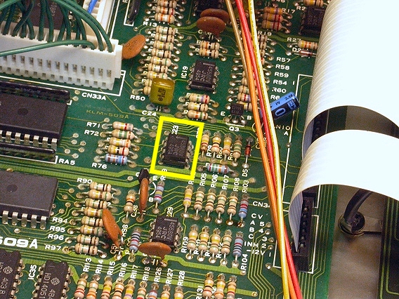
On the CPU board, the ATT & DEC control voltages come from the chip outlined in yellow. It's another 4558 op-amp, designated IC23. |
|
|
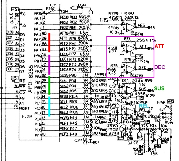
Here's IC23, outlined in violet, in the Korg Poly-61 schematic. It converts a stored digital number into an analog voltage. The conversion occurs as follows:
Since it's a 4-bit number, the Poly-61's Attack parameter has 16 possible values. We measured voltages as we changed Attack values on the front panel. The IC28 pins would alternate between high and low, but the op-amp's output was stuck at zero volts, indicating a bad IC23. |
|
| Korg® Poly-61M | ||
|---|---|---|
|
Last Page < |
Page Top ∧ |
Next Page > |
|
|
|
|
|
Page design and content Copyright © Richard Diemer - All rights reserved |