Prologue
|
Generally, the
capacitors
in your amp should be replaced only for a reason.
For example, a leaky filter capacitor in the amp's power supply might be
causing excessive hum and need replacement.
But indiscriminate re-capping of an old guitar amp may not be a
sound idea. It can waste time and money, trigger unexpected
problems, and change an amp's tone.
In fact, purposely changing an amp's tone is another reason for replacing a capacitor. In this case,
a certain capacitance value is either increased, decreased, or taken away.
To describe the effects of such changes, we'll look one by one at
the four basic functions that capacitors perform in a guitar amp:
-
Power supply filtering
-
Cathode bypassing
-
Stage coupling
-
Tone control
|
1: Power Supply Filter Caps
|
Filter capacitors in an amp's power supply smooth out pulsating DC (direct current)
coming from the amp's AC rectifier (the device that lets
current flow just one way). Filter capacitors store
electric charge as it flows in from the alternating house
current (the AC).
When the house current reverses direction, the stored charge is
there to power the amplifier. In other words, the filter caps make
possible a steady supply of voltage and current.
The primary filter cap is the one closest to the rectifier output.
It stores energy for the amp's output stage.
In the schematic below, the filter caps are outlined in blue. The primary capacitance, at point A,
consists of two 16 μF capacitors wired in parallel,
making the total primary capacitance 32 μF.
Subsequent filter caps, at points B and C,
store charge for earlier amp stages.
The resistors between the filter caps decouple the stages so they don't
interact, and also prevent overloading of the rectifier tube.
Fig. 1 —
Power Transformer, Full-Wave Rectifier,
Filter Capacitors
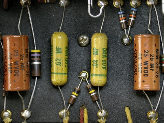
All power supply filter caps are "electrolytics".
Electrolytic caps contain an electrolyte (an ionic conducting paste) that causes an
oxide coating to form on the
positive plate
of the capacitor.
The thin coating serves as the insulating layer between the two
capacitor plates. Electrolytic caps can provide large
capacitance values in a small package.
All electrolytic caps are "polarized". The only
way they can be operated without damage is with a lower voltage on the
terminal marked "–".
|
Decreasing the Filter Capacitance
|
Decreasing the capacitance of a filter cap
decreases its storage space, making less charge available to power the
amp.
During peak demands, like a percussive bass note or a sudden chord, the
voltage supply will sag.
When the voltage supply sags, the gain of the amplifier goes down.
Then, when the demand subsides, the gain goes back up.
This gain compression can
be musically desirable, improving the "feel" of the amplifier
as it self-adjusts to the player's attack.
However, if you lower the filter capacitance by too much, unfiltered AC
hum can propagate through the amp.
|
Increasing the Filter Capacitance
|
Increasing the capacitance of a power supply filter cap lets it store
more electrons. Hence, there's a steadier supply of current, but at a lower
voltage since the charge is more spread out.
A steady supply of current reduces the gain
compression, yielding a truer, less spongy response.
But a lower supply voltage makes signals clip at a lower volume (right).
A steady supply of current also gives a tighter, more prominent bass.
That's because long duration, low-frequency waves need a larger store
of charge
than do short duration, high-frequency waves.
Raising the filter capacitance of a pre-amp's power supply
(point "C" in Fig. 1) can extend an amp's bass response but, in excess,
it can make the amp sound woofy, waste power on frequencies it can't
produce, or become unstable.
Raising the primary filter capacitance can damage
an amp by drawing too much current through its power
transformer and rectifier. Primary caps
aren't usually a target of modders.
|
2:
Cathode Bypass Caps
|
Cathode bypass caps are found in many amplifier circuits. To
describe their specific function, we'll first review Vacuum Tubes (aka
electronic valves) and Amplifier Bias.
|
Vacuum Tubes
|
Inside a vacuum tube, a
heated cathode
gives off electrons while a
positively-charged anode (aka plate) attracts and collects them. In this
way, an electron current flows through the tube.
In between the cathode and the anode of most tubes, there's a third
electrode. Called a control grid, it's a mesh that electrons must pass through on their way
from the cathode to the plate.
When a negative voltage is applied to the control grid, the positive
pull of the anode is partially negated, decreasing the flow of electrons
through the valve.
Furthermore, a fluctuating negative voltage on the control grid
causes a fluctuating electron current through the tube.
In this way, a small signal voltage is amplified into a heftier, more powerful signal current.
|
Amplifier Bias
|
When a vacuum tube is amplifying signals, the level of negativity on
its control grid is important. The starting value (before any
signal is applied) is called the "bias" value.
The negative bias must be more than the largest positive swing of the signal.
Otherwise, the grid would turn positive and siphon off electrons as
they pass through.
On the other hand, the bias mustn't be overly negative.
The bias is just right when the vacuum tube amplifies linearly (i.e. with its
output current directly proportional to its input signal).
|
Cathode Bias
|
A positive bias on a valve's cathode is equivalent to a negative bias on
its control grid – the control grid remains more negative than the cathode
and it continues to receive the signal voltage.
Cathode bias is created by a
resistor between the cathode and ground. Electrons flow up
through the resistor from ground, putting the cathode at a higher-than-ground
(positive)
potential.
|
Cathode Bypass Capacitors
|
Cathode bypass caps are wired in parallel with cathode bias
resistors in order to
conduct ac signals around the bias resistor (right).
Without a bypass cap, alternating current flows through the bias
resistor, alternating the valve's bias and linearity,
distorting the signal's dynamics.
Signal waveforms also distort. Wave crests add more bias, lowering the tube's gain, flattening
the crests, while wave troughs create less bias, raising the tube's gain,
deepening the troughs.
In Fig. 2, below, the cathode bypass caps are outlined in blue.
They're usually electrolytic types, unless smaller than 1 μF.
Note that points A, B, and C connect to the power supply in Fig. 1.
Decreasing & Increasing
Bypass Capacitance
|
As explained
here,
a small capacitance blocks low frequencies that a larger
capacitance would let pass.
Decreasing a cathode bypass capacitance forces
low frequencies through the bias resistor, increasing the tube bias and
decreasing the gain at those frequencies.
As a result, a smaller bypass cap yields less bass and more apparent treble
while a larger bypass cap yields more bass (if possible) and less
signal alteration.
|
Fig. 2 — Tone Capacitors, Coupling Capacitors,
and Cathode Bypass Capacitors
|
3:
Stage Coupling Caps
|
In the above schematic, stage coupling capacitors are outlined in red.
Their job is to pass ac signals from one amplifier stage
to the next while blocking any direct current.
A coupling cap that leaks direct current creates a dc voltage on
the input of the next stage. This voltage could interfere with
the bias of the stage or damage its parts.
|
Decreasing & Increasing
Coupling Capacitance
|
Since a small capacitance blocks more low frequencies than a large
capacitance, decreasing the coupling capacitance reduces the amount of bass passed
along to the next stage.
On the other hand, increasing the coupling capacitance allows more
bass to pass.
|
4:
Tone Control Caps
|
In Fig. 2, the tone control capacitors are outlined in green.
While the previous capacitor functions affected tone as a side effect, a tone cap's
sole function is to help shape the tone of the amplifier.
|
Changing Tone Capacitors
|
The effect of changing a tone cap depends on
the design of the tone control circuitry. There are many designs, including the simple one
shown in Fig. 2. Resistance values in a tone control circuit also play a role.
With your knowledge of how capacitors discriminate based on frequency, you can devise
substitution experiments.
Capacitance and resistance substitution boxes like those shown below can
speed up your exploration of alternate values for the various parts in
a tone control circuit.
Substitution Boxes for Capacitors and Resistors

Additional Resources:

|
®See trademark owners
HERE.
|